Login

Vi har for tiden tekniske problemer. Ditt skjema har ikke blitt innsendt. Vi beklager så mye og håper du vil prøve igjen senere. Detaljer:

Download

Register

Vi har for tiden tekniske problemer. Ditt skjema har ikke blitt innsendt. Vi beklager så mye og håper du vil prøve igjen senere. Detaljer:

Download

Thank you for registering

An email to complete your account has been sent to

Return to the website

get direct access

Fill in your details below and get direct access to content on this page

Text error notification

Text error notification

Checkbox error notification

Checkbox error notification

Vi har for tiden tekniske problemer. Ditt skjema har ikke blitt innsendt. Vi beklager så mye og håper du vil prøve igjen senere. Detaljer:

Download

Thank you for your interest

You now have access to F3SJ

A confirmation email has been sent to

Continue to page

Please or get direct access to download this document

F3SJ

F3SJ

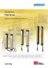
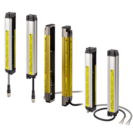
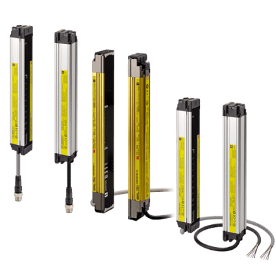
Offering the best selection of safety light curtains for your guarding needs.

Omron's F3SJ series of safety light curtains offer a tailored approach for a variety of production environments. Conventional safety light curtains offer full-featured models, even when only simple intrusion detection is needed. The F3SJ series offers a product range that allows you to choose the best product according to your application needs. The F3SJ series now allows you to select the best safety light curtain for your application environment without paying for unused functions.

Three F3SJ types allow easy selection for your application.

The EASY type (F3SJ-E)

  • For simple and affordable hand protection
  • Easy to install
  • Mounting now takes less than half the man-hours that conventional models take.
The BASIC type (F3SJ-B)
  • For simple hand protection, series connection and muting functions
  • The muting function allows use of the safety light curtain in a variety of manufacturing environments. 
  • The flexible mounting supports up to three sets of series-connected sensors.
The ADVANCED type (F3SJ-A)
  • For finger protection and series connection
  • The detection capability supports finger protection through use of 14mm resolution 
  • Has a wide variety of muting and blanking functions to increase productivity.

Specifications & ordering info

Ordering information

Application

Detection capability

Beam gap

Operating range

Protective height (mm)

Order code

Finger protection

Dia. 14 mm

9 mm

0.2 to 9 m

245 to 1,631

F3SJ-A ____ P14

Hand/arm protection

Dia. 30 mm

25 mm

0.2 to 9 m

245 to 1,620

F3SJ-A ____ P30

0.2 to 7 m

1,745 to 2,495

Safety light curtain model list

F3SJ-A14 series (9 mm gap), F3SJ-A14 TS series (9 mm gap)

Number of beams

Protective height (mm)1

Order code

26

245

F3SJ-A0245P14

28

263

F3SJ-A0263P14

34

317

F3SJ-A0317P14

42

389

F3SJ-A0389P14

50

461

F3SJ-A0461P14

60

551

F3SJ-A0551P14

68

623

F3SJ-A0623P14

76

695

F3SJ-A0695P14

80

731

F3SJ-A0731P14

88

803

F3SJ-A0803P14

96

875

F3SJ-A0875P14

108

983

F3SJ-A0983P14

116

1,055

F3SJ-A1055P14

124

1,127

F3SJ-A1127P14

132

1,199

F3SJ-A1199P14

140

1,271

F3SJ-A1271P14


F3SJ-A30 series (25 mm gap)

Number of beams

Protective height (mm)2

Order code

10

245

F3SJ-A0245P30

12

295

F3SJ-A0295P30

16

395

F3SJ-A0395P30

19

470

F3SJ-A0470P30

21

520

F3SJ-A0520P30

22

545

F3SJ-A0545P30

23

570

F3SJ-A0570P30

25

620

F3SJ-A0620P30

29

720

F3SJ-A0720P30

32

795

F3SJ-A0795P30

35

870

F3SJ-A0870P30

37

920

F3SJ-A0920P30

38

945

F3SJ-A0945P30

41

1,020

F3SJ-A1020P30

44

1,095

F3SJ-A1095P30

45

1,120

F3SJ-A1120P30

48

1,195

F3SJ-A1195P30

51

1,270

F3SJ-A1270P30

56

1,395

F3SJ-A1395P30

65

1,620

F3SJ-A1620P30

70

1,745

F3SJ-A1745P30

75

1,870

F3SJ-A1870P30

80

1,995

F3SJ-A1995P30

90

2,245

F3SJ-A2245P30

95

2,370

F3SJ-A2370P30

100

2,495

F3SJ-A2495P30

Accessories (sold separately)

Single-end connector cable (2 cables per set, for emitter and receiver)

For wiring with safety circuit such as single safety relay, safety relay unit, and safety controller.


Appearance

Cable length

Specifications

Order code


3 m

M12 connector (8-pin)

F39-JD3A

7 m

F39-JD7A

10 m

F39-JD10A

15 m

F39-JD15A

20 m

F39-JD20A

Setting Tools

Appearance

Type

Remarks

Order code


“SD Manager”
Setting support software
for the F3SJ

Accessories:

SD Manager CD-ROM (1),

F39-CN1 branch connector (1),

Connector cap (1),
2-m Dedicated cable (1),
0.3-m Dedicated cable with plug (1),
Instruction manual

F39-GWUM

Sensor Mounting Brackets (Sold separately)

Appearance

Specifications

Application

Remarks

Order code


Standard mounting bracket
(for top/bottom)

(provided with the F3SJ)

2 for an emitter,
2 for a receiver,
total of 4 per set

F39-LJ1


Flat side mounting bracket

Use these small-sized brackets when performing side mounting with standard mounting brackets, so that they do not protrude from the detection surface.

2 for an emitter,
2 for a receiver,
total of 4 per set

F39-LJ2


Free-location mounting bracket
(also used as standard intermediate bracket)

Use these brackets for mounting on any place without using standard bracket.

Two brackets
per set

F39-LJ3


F3SN Intermediate bracket
Replacement spacers

When replacing the F3SN with the F3SJ, the mounting hole pitches in the Intermediate Brackets are not the same. This Spacer is placed between the mounting holes to mount the F3SJ.

1 set with
2 pieces

F39-LJ3-SN


Top/bottom bracket B
(mounting hole pitch 19 mm)

Mounting bracket used when replacing existing area sensors (other than F3SN or F3WN) with the F3SJ.
For front mounting.

Suitable for mounting hole pitch of 18 to 20 mm.

2 for an emitter,
2 for a receiver,
total of 4 per set

F39-LJ4


Bracket for replacing
short-length F3SN

Mounting bracket used when an F3SN with protective height of 300 mm or less is replaced by an F3SJ.

2 for an emitter,
2 for a receiver,
total of 4 per set

F39-LJ5


Space-saving mounting bracket

Use these brackets to mount facing inward.
Length is 12 mm shorter than the standard
F39-LJ1 bracket.

2 for an emitter,
2 for a receiver,
total of 4 per set

F39-LJ8


Top/bottom bracket C (mounting hole pitch 13 mm)

Mounting bracket used when replacing existing area sensors having a mounting pitch of 13 mm with the F3SJ.

2 for an emitter,
2 for a receiver,
total of 4 per set

F39-LJ11

Laser pointer

Appearance

Output

Order code


Laser pointer for F3SJ

F39-PTJ

Specifications

F3SJ-A ____ P14/P30

Model

F3SJ-A ____ P14

F3SJ-A ____ P30

Sensor type

Type 4 safety light curtain

Version

Ver. 2

Setting tool connection

Connectable

Safety category

Safety purpose of category 4, 3, 2, 1, or B

Detection capability

Opaque objects 14 mm in diameter

Opaque objects 30 mm in diameter

Beam gap (P)

9 mm

25 mm

Number of beams (n)

26 to 180

10 to 100

Protective height (PH)

245 to 1,631 mm

245 to 2,495 mm

Lens diameter

Diameter 5 mm

Operating range

0.2 to 9 m (protective height 1,640 mm max.), 0.2 to 7 m (protective height 1,655 mm min.)
(Depending on the setting tool, the detection distance can be shortened to 0.5 m.)

Response time
(under stable light incident condition)

ON to OFF

1 set, 0245 to 983: 11 ms to 17.5 ms max.

1,055 or higher: 20 ms to 25 ms max.

1 set: 10 ms to 17.5 ms max.

OFF to ON

1 set, 0245 to 983: 44 ms to 70 ms max.

1,055 or higher: 80 ms to 100 ms max.

1 set: 40 ms to 70 ms max.

Startup waiting time

2 s max. (2.2 s max. for series connection)

Power supply voltage (Vs)

24 VDC±20% (ripple p-p10% max.)

Current consumption
(no load)

Emitter

To 50 beams: 76 mA max., 51 to 100 beams: 106 mA max., 101 to 150 beams: 130 mA max.,

151 to 180 beams: 153 mA max., 201 to 234 beams: 165 mA max.

Receiver

To 50 beams: 68 mA max., 51 to 100 beams: 90 mA max., 101 to 150 beams: 111 mA max.,

151 to 180 beams: 128 mA max., 201 to 234 beams: 142 mA max.

Light source (emitted wavelength)

Infrared LED (870 nm)

Effective aperture angle (EAA)

Based on IEC 61496-2.Within±2.5° for both emitter and receiver when the detection distance is 3 m or over

Safety outputs (OSSD)

Two PNP transistor outputs, load current 300 mA max., residual voltage 2 V max. (except for voltage drop due to cable extension),
allowable capacity load 2.2 μF, leak current 1 mA max.

(This can be different from traditional logic (ON/OFF) because safety circuit is used.)

Auxiliary output 1
(Non-safety output)

One PNP transistor output, load current 300 mA max., residual voltage 2 V max. (except for voltage drop due to cable extension),
leak current 1 mA max.

Auxiliary output 2

(Non-safety output. Function for Basic System.)

One PNP transistor output, load current 50 mA max., residual voltage 2 V max. (except for voltage drop due to cable extension),
leak current 1 mA max.

External indicator output
(Non-safety output)

Available indicators

Incandescent lamp : 24 VDC, 3 to 7 W

LED lamp: Load current 10 mA to 300 mA max., leak current 1 mA max.
(To use an external indicator, an F39-JJ3N universal indicator cable or an F39-A01P-PAC dedicated external indicator kit is required.)

Output operation mode

Receiver

Safety output 1, 2: ON when receiving light

Auxiliary output 1: Inverse of safety output signals (Operation mode can be changed with the setting tool.)

External indicator output 1 : Inverse of safety output signals for a basic system (Operation mode can be changed with the setting tool.), ON when muting/override for a muting system (Operation mode can be changed with the setting tool.)

Emitter

Auxiliary output 2: Turns ON when the point of 30,000 operating hours is reached (Operation mode can be changed with the setting tool.)

External indicator output 2 : ON when lock-out for a basic system (Operation mode can be changed with the setting tool.)
ON when muting/override for a muting system (Operation mode can be changed with the setting tool.)


Model

F3SJ-A ____ P14

F3SJ-A ____ P30

Input voltage

Test input, interlock selection input, reset input, and muting input are all

ON voltage: 9 to 24 V (Vs) (sink current: 3 mA max.), OFF voltage: 0 to 1.5 V, or open

External device monitoring input

ON voltage: 9 to 24 V (Vs) (sink current: 5 mA max.), OFF voltage: 0 to 1.5 V, or open

Indicator

Emitter

Light intensity level indicators (green LED × 2, orange LED × 3): ON based on the light intensity

Error mode indicators (red LED × 3): Blink to indicate error details

Power indicator (green LED × 1): ON while power is on

Interlock indicator (yellow LED × 1): ON while under interlock, blinks at lockout.

External device monitoring indicator (muting input 1 indicator), Blanking/test indicator (muting input 2 indicator) (green LED × 2):
ON/flash according to function

Receiver

Light intensity level indicators (green LED × 2, orange LED × 3): ON based on the light intensity

Error mode indicators (red LED × 3): Blink to indicate error details

OFF output indicator (red LED × 1): ON when safety output is OFF, blinks at lockout.

ON output indicator (green LED × 1): ON while safety output is ON

Muting error indicator, Blanking/test indicator (green LED × 2): ON/flash according to function

Mutual interference prevention function

Interference light prevention algorithm, sensing distance change function

Series connection

Time division emission by series connection

Number of connections: up to 4 sets (F3SJ-A only) F3SJ-E, F3SJ-B and F3SJ-TS cannot be connected.

Total number of beams: up to 400 beams

Maximum cable length for 2 sets: no longer than 15 m

Test function

Self test (at power-ON and at power distribution)

External test (emission stop function by test input)

Safety-related functions

Start interlock, restart interlock (Must be set with a setting tool when the muting function is used.)

External device monitor

Muting (Lamp burnout detection, override function included. F39-CN6 key cap for muting is required.)

Fixed blanking (must be set by a setting tool)

Floating blanking (must be set by a setting tool)

Connection method

Connector method (M12, 8-pin)

Protection circuit

Output short-circuit protection, and power supply reverse polarity protection

Ambient temperature

Operating: -10 to 55°C (no icing), Storage: -30 to 70°C

Ambient humidity

Operating: 35% to 85% (no condensation), Storage: 35% to 95%

Operating ambient light intensity

Incandescent lamp: receiving-surface light intensity of 3,000 lx max., Sunlight: receiving-surface light intensity of 10,000 lx max.

Insulation resistance

20 MΩ min. (at 500 VDC)

Withstand voltage

1,000 VAC 50/60 Hz, 1 min

Degree of protection

IP65 (IEC 60529)

Vibration resistance

Malfunction: 10 to 55 Hz, Multiple amplitude of 0.7 mm, 20 sweeps in X, Y, and Z directions

Shock resistance

Malfunction: 100 m/s2, 1,000 times each in X, Y, and Z directions

Material

Casing (including metal parts on both ends): Aluminum, zinc die-cast

Cap: ABS resin, Optical cover: PMMA resin (acrylic), Cable: Oil resistant PVC

Weight (packaged)

Calculate using the following expressions:

(1) For F3SJ-A ____ 14, weight (g) = (protective height) x 1.7 + α

(2) F3SJ-A ____ 30, weight (g) = (protective height) x 1.5 + α

The values for α are as follows:

Protected height 245 to 596 mm: = 1,100 protected height 1,660 to 2,180 mm: = 2,400

Protected height 600 to 1,130 mm: = 1,500 protected height 2,195 to 2,500 mm: = 2,600

Protected height 1,136 to 1,658 mm: = 2,000

Accessories

Test rod ( * 1), instruction manual, standard mounting bracket (F39-LJ1 bracket for top/bottom mounting), mounting brackets (intermediate) ( * 2), error mode label, User's Manual (CD-ROM)

* 1. The F3SJ-A ☐☐☐☐ 55 is not included.
* 2. Number of intermediate brackets depends on protective height of F3SJ.

For protective height from 600 to 1,130 mm : 1 set for each of the emitter and receiver is included

For protective height from 1,136 to 1,658 mm: 2 sets for each of the emitter and receiver are included

For protective height from 1,660 to 2,180 mm : 3 sets for each of the emitter and receiver are included

For protective height from 2,195 to 2,500 mm : 4 sets for each of the emitter and receiver are included

Applicable standards

IEC 61496-1, EN 61496-1 UL 61496-1, Type 4 ESPE (Electro-Sensitive Protective Equipment)

IEC 61496-2, CLC/TS 61496-2, UL 61496-2, Type 4 AOPD (Active Opto-electronic Protective Devices)

IEC 61508-1 to -3, EN 61508-1 to -3 SIL3

IEC 13849-1: 2006, EN ISO 13849-1: 2008 (PLe, Cat.4)

UL 508, UL 1998, CAN/CSA C22.2 No.14, CAN/CSA C22.2 No.0.8

Response Time

Model

Protected height (mm)

Number of beams

Response time ms (ON to OFF)

Response time ms (OFF to ON)

F3SJ-A ____ 14 Series

245 to 263

26 to 28

11

44

281 to 389

30 to 42

12

48

407 to 497

44 to 54

13

52

515 to 605

56 to 66

14

56

623 to 731

68 to 80

15

60

767 to 983

84 to 108

17.5

70

1,055 to 1,271

116 to 140

20

80

1,343 to 1,559

148 to 172

22.5

90

1,631

180

25

100

F3SJ-A ____ 30 Series

245 to 395

10 to 16

10

40

420 to 720

17 to 29

11

44

745 to 1,045

30 to 42

12

48

1,070 to 1,295

43 to 52

13

52

1,395 to 1,620

56 to 65

14

56

1,745 to 1,995

70 to 80

15

60

2,120 to 2,495

85 to 100

17.5

70

Note: Use the following expressions for series connection.

  • For 2-set series connection:
    Response time (ON to OFF): Response time of the 1st unit + Response time of the 2nd unit - 1 (ms), Response time (OFF to ON): Response time calculated by the above × 4 (ms)
  • For 3-set series connection:
    Response time (ON to OFF):

    Response time of the 1st unit + Response time of the 2nd unit + Response time of 3rd unit - 5 (ms), Response time (OFF to ON): Response time calculated by the above × 5 (ms)
    For models with the “-TS” suffix, multiply the response time obtained by the above × 5 (ms), or use 200 ms, whichever is less.)
  • For 4-set series connection:
    Response time (ON to OFF): Response time of the 1st unit + Response time of the 2nd unit + Response time of the 3rd unit + Response time of the 4th unit - 8 (ms)
    Response time (OFF to ON): Response time calculated by the above × 5 (ms)

Cable extension length

Total cable extension length must be no greater than the lengths described below.

When the F3SJ and an external power supply are directly connected, or when the F3SJ is connected to a G9SA-300-SC.

Condition

1 set

2 sets

3 sets

4 sets

Using incandescent lamp for auxiliary output and external indicator output

45 m

40 m

30 m

20 m

Not using incandescent lamp

100 m

60 m

45 m

30 m


When connected to the F3SP-B1P

Condition

1 set

2 sets

3 sets

4 sets

Using incandescent lamp for external indicator output 2

40 m

30 m

25 m

20 m

Using incandescent lamp for external indicator output 1

60 m

45 m

30 m

20 m

Using incandescent lamp for auxiliary output 1

Not using incandescent lamp

100 m

60 m

45 m

30 m

Note: Keep the cable length within the rated length. Failure to do so is dangerous as it may prevent safety functions from operating normally.

Connections

Basic Wiring Diagram

PNP Output

Wiring when using manual reset mode, external device monitoring.


1. Protective height (mm) = Total sensor length

2. Protective height (mm) = Total sensor length

1. Protective height (mm) = Total sensor length

2. Protective height (mm) = Total sensor length

How can we help you?

If you have a question or would like to ask for a quote, please contact us or send a request.

+47 22 65 75 00
Contact us

Kontakt meg F3SJ

f3sj series 600x600 prod

Vennligst fyll inn alle obligatoriske felter. Dine personlige opplysninger vil bli behandlet konfidensielt.
Text error notification

Text error notification

Text error notification

Text error notification

Country error notification

Text area error notification

Checkbox error notification

Checkbox error notification

Takk for din forespørsel. Vi vil kontakte deg så snart som mulig.

Vi har for tiden tekniske problemer. Ditt skjema har ikke blitt innsendt. Vi beklager så mye og håper du vil prøve igjen senere. Detaljer:

Download
+47 22 65 75 00
+47 22 65 75 00
Request quotation
Request quotation

Tilbud for F3SJ

Ved å fylle ut dette skjemaet vil du motta et tilbud på det valgte produktet. Vennligst fyll inn alle obligatoriske felter. Dine personlige opplysninger vil bli behandlet konfidensielt.

f3sj series 600x600 prod

Personlige opplysninger

F3SJ

Text error notification

Text error notification

Text error notification

Text error notification

Country error notification

Tilbudsdetaljer

Select notification error

Select notification error

Text area error notification

Checkbox error notification

Checkbox error notification

Takk for din tilbudsforespørsel. Vi vil sende deg det forespurte tilbudet så snart som mulig.

Vi har for tiden tekniske problemer. Ditt skjema har ikke blitt innsendt. Vi beklager så mye og håper du vil prøve igjen senere. Detaljer:

Download
Request quotation
Request quotation

Downloads

download
EAC Mark removal Merknad for å avslutte bruk
enPDF 220,8 kB
download
F3SJ Safety Light Curtain Datablad
enPDF 22,5 MB
download
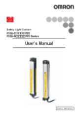
F3SJ-A Brukermanual
enPDF 8,2 MB
download
F3SJ-A SD Manager v1.40 Konfigurator
enZIP 325,4 MB
download
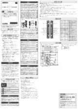
F3SJ-A____N__ Instruksjonsblad
enPDF 116,5 kB
download
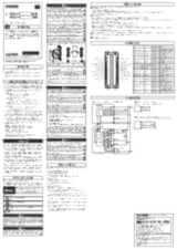
F3SJ-B_N25-01T Instruksjonsblad
enPDF 5 MB
download
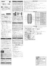
F3SJ-B_P25-01TS Instruksjonsblad
enPDF 758,5 kB
download
F3SJ-B_P25-02TS Instruksjonsblad
enPDF 750,3 kB
download
F3SJ-E/-B Brukermanual
enPDF 5,1 MB
download
F3SJ-A Brukermanual
enPDF 8,2 MB
download
F3SJ-A____N__ Instruksjonsblad
enPDF 116,5 kB
download
F3SJ-B_N25-01T Instruksjonsblad
enPDF 5 MB
download
F3SJ-B_P25-01TS Instruksjonsblad
enPDF 758,5 kB
download
F3SJ-B_P25-02TS Instruksjonsblad
enPDF 750,3 kB
download
F3SJ-E/-B Brukermanual
enPDF 5,1 MB
download
F3SJ-E_-B_N25 Instruksjonsblad
enPDF 671,4 kB
download
F3SJ-E_-B_P25 Instruksjonsblad
enPDF 666,9 kB