ZG2
Easy profile measurement - Teach & Go
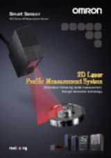
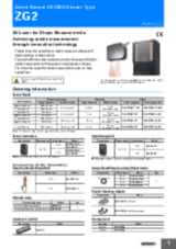
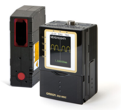
The ZG2 enables precise shape measurement on challenging materials and surfaces. An easy and intuitive user interface enables efficient installation, setup and operation. A built-in LCD monitor indicates the measurement result in real time.
- Easy-to-use - intuitive user interface
- Live - built-in LCD monitor for setup and immediate profile display
- Versatile - 18 measurement tools
- Accurate - 5 µm resolution (3 mm / 631 pixels)
- Wide profiles - up to 70 mm
Specifications & ordering info
Ordering information
Sensor heads
Note: - For details, refer the ratings and specifications table.
- Designate the cable length (0.5 m, 2 m) when ordering.
Sensor controllers
Accessories (order separately)
Real-time parallel output unit
RS-232C cable
Sensor head extension cable
Parallel mounting adaptor
Controller link unit
Memory card
Specifications
Sensor heads
|
1
undefined
|
||||||||
|
Linearity (in the height direction)
2
undefined
|
||||||||
|
3
undefined
|
||||||||
|
5 mW max. output, 1 mW max. exposure (without using optical instruments) |
||||||||
|
Class 2M of EN60825-1 / IEC60825-1 |
Class 2 of EN60825-1 / IEC60825-1 |
|||||||
|
Beam shape (at measurement center distance)
4
undefined
|
||||||||
|
STANDBY: Lights when laser irradiation preparation is complete (indication color: green) |
||||||||
|
LD_ON: Lights when the laser is irradiating (indication color: green) |
||||||||
|
Illumination on the photo-receiving face 7,000 lx max.: Incandescent lamp |
||||||||
|
Operating: 0 to 50°C, Storage: -15 to 60°C (with no icing or condensation) |
||||||||
|
10 to 150 Hz with 0.35 mm single amplitude for 80 min each in X, Y, and Z directions |
||||||||
|
150 m/s², 3 times each in 6 directions (up / down, right / left, forward / backward) |
||||||||
|
Case: Aluminum diecast, Front cover: Glass, Cable insulation: Heat-resistive polyvinyl chloride (PVC), |
||||||||
|
Laser labels (EN: 2 labels, FDA: 3 labels), Ferrite core (1), Instruction manual |
||||||||
*1 Obtained by setting an Omron standard measurement object at the measurement center distance and determing the average height of the beam line. The conditions are given in the table below. However, satisfactory resolution cannot be attained in strong electromagnetic fields.The minimum resolution of the ZG2-WDS8T/WDS3VT is 0.25 ƒÊm, even when the average number of operations is increased. Resolution does not go any lower.
*2 The tolerance for an ideal straight line obtained by determing the average height of an Omron standard measurement object for the beam line. The CCD high-resolution mode is used. Linearity varies depending on the measurement object.
*3 A value attained by using an aluminum jig to secure the distance between the Sensor head and the measurement object. The CCD standard mode is used.
*4 Defined as 1/e 2 (13.5%) of the center light intensity. This may be influenced when light leakage also exists outside the defined area and the reflectivity of the light around the measurement object is higher than that of the measurement object.
Sensor controllers
|
2
2.
The image input periods listed here are for fixed/auto sensitivity. The image input period will be longer for multi-sensitivity, high-speed multi-sensitivity, or other settings. When the high-power mode is ON, the shortest image input period is 95 ms regardless of the setting of the CCD mode. Use the eco monitor in the RUN mode to determine the actual image input period.
|
16 ms (high-precision mode), 8 ms (standard mode), 5 ms (high-speed mode) |
|||
|
Select voltage or current (using the sliding switch on the bottom surface) |
||||
|
ON: Power supply voltage short or |
||||
|
Height, 2-point Step, 3-point Step, Edge position, Edge width, Angle, Intersection coordinates, Intersection angle, Sectional area |
||||
|
Filter, Laser power adjustment, Position correction (height, position, lope), Linked operation, Point of inflection measurement |
||||
|
1,000 VAC, 50 / 60 Hz for 1 min between lead wires and Controller case |
||||
|
Operating: 0 to 50°C, Storage: -15 to 60°C (with no icing or condensation) |
||||
|
Vibration frequency: 10 to 150 Hz, single amplitude: 0.35 mm, acceleration: 50 m/s² |
||||
|
150 m/s², 3 times each in 6 directions (up/down, right/left, forward/backward) |
||||
|
Approx. 300 g (including cable) (Packed state: Approx. 450 g) |
||||
|
ZG2-WDC_1: Large Ferrite Core (1 piece), Instruction Manual ZG2-WDC_1A: Large Ferrite Core (1 piece), Small Ferrite Core (2 pieces), Instruction Manual, Setup Support Software (CD-ROM), USB cable (1 m) |
||||
Data storage unit
2. The image input periods listed here are for fixed/auto sensitivity. The image input period will be longer for multi-sensitivity, high-speed multi-sensitivity, or other settings. When the high-power mode is ON, the shortest image input period is 95 ms regardless of the setting of the CCD mode. Use the eco monitor in the RUN mode to determine the actual image input period.
5. Data is saved in the memory of the main unit during logging. The data is automatically saved in a memory card after logging is completed. The maximum number of logging differs according to set conditions. For details, refer to the Users Manual.
Need assistance?
We’re here to help! Reach out, and our specialists will assist you in finding the best solution for your business.
Kontakt meg ZG2
Takk for din forespørsel. Vi vil kontakte deg så snart som mulig.
Vi har for tiden tekniske problemer. Ditt skjema har ikke blitt innsendt. Vi beklager så mye og håper du vil prøve igjen senere. Detaljer:
DownloadTilbud for ZG2
Ved å fylle ut dette skjemaet vil du motta et tilbud på det valgte produktet. Vennligst fyll inn alle obligatoriske felter. Dine personlige opplysninger vil bli behandlet konfidensielt.
Takk for din tilbudsforespørsel. Vi vil sende deg det forespurte tilbudet så snart som mulig.
Vi har for tiden tekniske problemer. Ditt skjema har ikke blitt innsendt. Vi beklager så mye og håper du vil prøve igjen senere. Detaljer:
DownloadFeatures
Width - Car body
The sensor checks the correct width between different parts of the car body.
Bottom PCB board
The sensor checks the warpage of a PCB board to avoid soldering or connection defects.
Area glue bead
The sensor checks the area (shape) of the glue to control the continuous motion of a robot.
Position – Sheet
The sensor checks the wandering of paper over time in order to detect drifts.
Angle – Seat
The sensor checks the differences of seat angles. The controller allows you to calculate various angles via the definition of additional tasks.
Downloads